How It Works
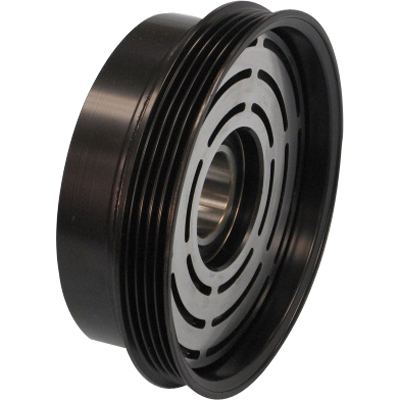
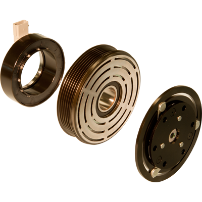
The clutch assembly consists of three components: the rotor assembly, armature assembly, and the field coil assembly.
The rotor assembly is driven by the front end accessory drive (FEAD) belt, and is always rotating when the vehicle’s engine is running. Nested inside the rotor is the field coil assembly, which is stationary. The armature assembly consists of a hub which is fixed to the driven shaft of the accessory, and a disc, which through some sort of flexible member, is able to move axially relative to the hub.
There is a small gap between the face of the rotor assembly and the armature assembly disc when the accessory is not required, allowing the rotor assembly to rotate freely with the FEAD belt.
The field coil assembly contains a magnet wire coil that is electrically connected to the vehicle’s wiring harness. When demand for the accessory exists, current flows through the field coil assembly magnet wire, creating an electromagnetic field. This electromagnetic field draws the armature assembly disc into contact with the rotor assembly, and the armature assembly rotates with the rotor assembly, driving the accessory.
Rotor Assembly
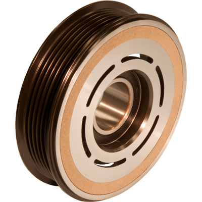
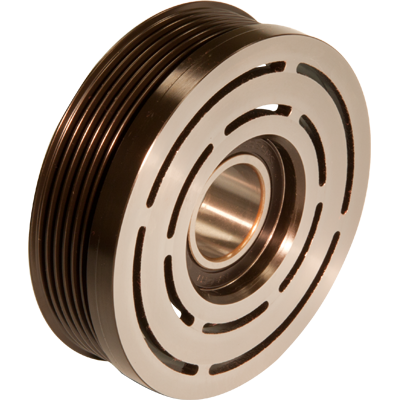
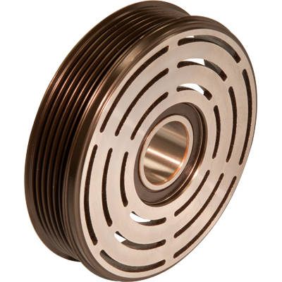
The rotor assembly has two main components: the rotor and the bearing. The rotor is made from low carbon steel, and has grooves to accept the FEAD belt profile on the outer diameter, and a bore to house the bearing on the inner diameter. The number of grooves, the groove diameter, and the axial location of the groove profile are some of the application-specific design parameters for the rotor. Depending upon the design, the construction of the rotor may consist of one piece of steel, or two or more pieces welded together.
The friction surface has two or three rings of slots, called banana slots. These slots help define the magnetic flux path between the rotor and armature. The slots concentrate the magnetic flux, and force it to pass back and forth between the rotor and armature friction surfaces. Each time the magnetic flux travels from one member to the other, an electromagnetic pole exists. These poles define the points of electromagnetic attraction between the rotor and armature, and generally speaking the more poles there are, the stronger the attraction between the two components. Depending upon several design factors, it may be preferred to have two rings of slots (4 poles) or 3 rings of slots (6 poles).
To increase the torque capacity of the clutch, one option is to add friction material to the friction surface of the rotor. Friction material may offer other benefits as well, such as extending the operating life of the clutch by reducing wear on the friction surfaces.
The bearing is typically a double row ball bearing, and it permits the rotor to rotate while mounted on the nose of the accessory. Located between the inner and outer diameters is the friction surface, which is used to drive the armature.
Field Coil Assembly
The field coil assembly consists of a housing, a magnet wire coil, and a method of electrically connecting the coil with the vehicle wiring harness. The housing is a low carbon steel forging or stamping. The electrical connection is through either a lead wire assembly or integral connector assembly. While the basics of operation are the same for any type of coil, there are several different types of coil assemblies available, to meet the requirements of each specific application.
Bobbin / Staked Cover
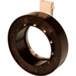
The magnet wire coil is nested between a plastic bobbin and a plastic cover, with the magnet wire leads extending from the top of the bobbin. The bobbin/coil/cover subassembly is then inserted into the coil housing, with the magnet wire leads extending through a window in the housing, and the cover being exposed on the open end of the housing. The cover is then staked in place, securing the coil winding in the housing. Terminations are then made between the magnet wire and lead wire assembly or integrated connector terminals. While this type of construction lends itself to low-cost automated assembly, the mechanically staked cover is not watertight.
Epoxy
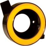
The magnet wire is either wound on a bobbin or wrapped with cotton tape. Lead wires are attached to the coil winding and the coil assembly is inserted in the coil housing. The subassembly is preheated, and then liquid epoxy is dispensed on the coil assembly in the housing. After curing the epoxy in an oven, the lead wires are terminated with the wiring harness connectors. The epoxy coil design is completely water proof.
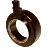
Injection Molding
The magnet wire is either wound on a bobbin or wrapped with cotton tape and inserted in the coil housing. A terminal subassembly is attached to the winding to facilitate either a lead wire or integral connector assembly. The whole assembly is then injection molded, including over molding of the terminal assembly for a water tight coil assembly.
| Coil Type | Integral Connector Available | Lead Wire Available | Integral Diode Available | Waterproof | Integral Thermal Fuse | Relative Cost |
|---|---|---|---|---|---|---|
| Bobbin & Staked Cover | Yes | Yes | Yes | No | Yes | Lowest |
| Epoxy Filled | No | Yes | Yes | Yes | Yes | Higher |
| Injection Molded | Yes | Yes | Yes | Yes | Yes | Highest |
Armature Assembly
The armature assembly has three main components, which are riveted together. They include the hub, which is typically bolted to the accessory input shaft; the armature disc, which has a friction surface that contacts the rotor upon clutch engagement; and a flexible member which allows the armature disc to move axially relative to the hub.
Various armature designs are available. These designs have different application and performance characteristics, such as the packaging envelope required, level of engagement and disengagement noise, vibration dampening characteristics, flexible member spring rate, and cost. The distinguishing feature between the different designs is the type of mechanism used that permits the armature disc to move axially and engage the rotor friction surface.
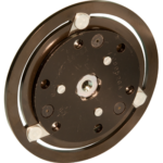
Leaf Spring
This is the simplest, most compact and least expensive armature design. The armature disc is attached to the hub through three leaf springs, which defect and allow the disc to contact the rotor friction surface upon engagement, and drive the accessory. Since the springs can only carry a load under tension, torque can be transmitted in only one direction.
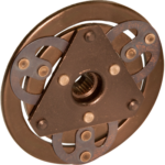
Ring Spring
Utilization of ring springs in place of the leaf springs creates a very robust and compact design, which reduces noise and vibration issues associated with accessory pulsations. Additionally, the ring spring design is bi-directional.
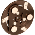
Rivet Damper
The rivet damper, based on the leaf spring design, is a simple, compact mechanism that absorbs armature disc vibrations, axial vibrations induced by the accessory as well as engagement noise. The rivet damper design is directional.
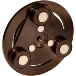
Three Eye
The three eye design utilizes three rubber dampers that provide a cushion between rivets attached to the armature disc and a drive plate attached to the hub. This design reduces noise and vibration during clutch engagement and disengagement as well as absorbs accessory induced vibration and pulsations. This design is bi-directional and is economically priced.
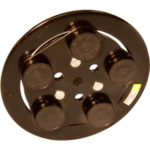
Five Eye
The five eye design works on the same principle as the three eye, but provides even better noise and vibration dampening. Generally the five eye is utilized on larger accessories that induce larger vibrations. Also, the five eye design is bi-directional.
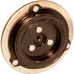
ARTC
The annular ring torque cushion design has the best engagement and disengagement noise characteristics, and is also the best in absorbing accessory induced pulsations and vibrations. It is bi-directional, and also the most expensive.
| Armature Type | Application Size | Dampening Capability | Bi-directional | Relative Cost |
|---|---|---|---|---|
| Leaf Spring | Smallest | Lowest | No | Lowest |
| Ring Spring | Smallest | Lower | Yes | Lower |
| Rivet Damper | Smallest | Middle | No | Middle |
| 3 Eye | Larger | Middle | Yes | Middle |
| 5 Eye | Larger | Better | Yes | Higher |
| ARTC | Larger | Best | Yes | Highest |
Over Torque Protection Device
On a constant run application there is a need to disengage the drive belt should you have internal failure of the driven component. For these applications we have developed a mechanical torque transfer device that disengages should a predetermined torque load exist, which is generally the result of the component internal failure. This minimizes the potential of a ‘walk home’ situation with the use of serpentine drive single belt FEAD systems.
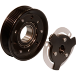
Fan Control
The Fan Control coil includes an integral PC Board that provides data to the system control module. Various data is compiled so that the correct voltage / amperage is applied to the coil for optimum viscous clutch operation and, ultimately, optimum engine cooling performance.
